Litchi Missions vs DJI Fly Missions

Differences Between Waypoint Paths in Litchi and DJI Fly
Two waypoint missions built from the same set of coordinates can produce very different flight paths depending on whether they're created in Litchi or DJI Fly. The difference comes from the mathematical method each system uses to turn waypoints into a smooth, flyable curve
Historically:
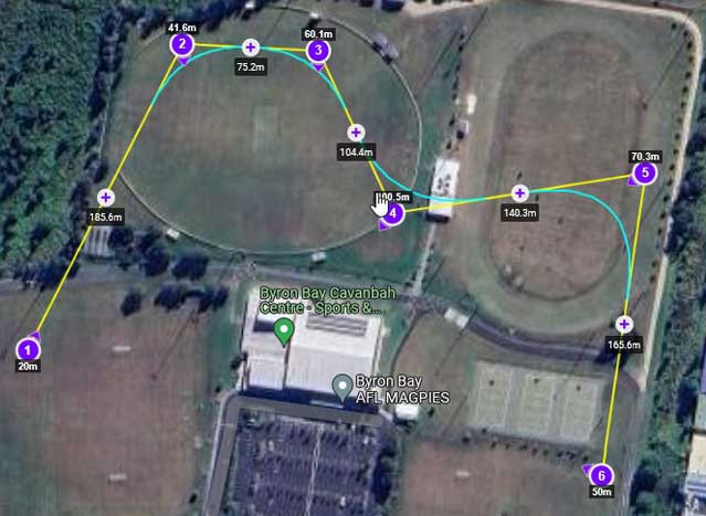
- Litchi curved missions produced a path with rounded corners that did not pass through interior waypoints.
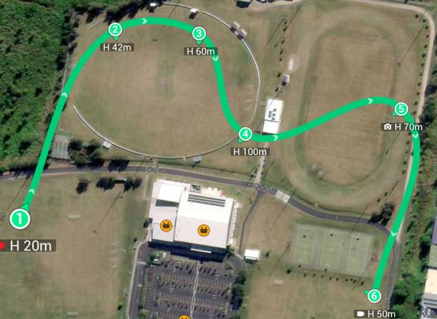
- DJI Fly missions generated a curve that always passes through every waypoint.
However, this distinction is no longer absolute. The latest version of Litchi's Mission Hub now supports both styles (depending on the drone being used), allowing you to choose:
- Traditional Litchi curved paths (straight lines, rounded corners, stays inside the convex hull)
- New "Smooth Curve" paths (DJI-style interpolation passing through every waypoint)
This update means Litchi can now replicate DJI Fly's behavior when desired, whil still offering its original straight-line with curves method.
|
|
Why Litchi and DJI Fly Produce Different Paths
Even when two missions share the same set of waypoints, their paths may differ. Some of these differences include:
- Traditional curved Litchi missions do not pass through the interior waypoints while DJI Fly waypoint missions do pass through all waypoints.
- Litchi supports both curved and straight-line missions while DJI Fly only directly supports curved missions. The WPML language used by DJI does supports both straight line missions and curved missions. DJI drones can fly straight line and curved mission. However, DJI Fly's implementation only supports the creation of curved missions.
- Litchi enables the curved portions of the missions to be adjusted while the curves in DJI Fly missions have a fixed curvature.
- The "Convex Hull" property of Litchi missions means that the mission path is guaranteed to be confined within the convex hull of the waypoints. DJI Fly missions do not have this property and therefore, DJI's path can travel outside of the convex hull defined by the waypoints.
Perhaps the most important of those differences is the fact that DJI Fly missions (or Litchi missions using the DJI Engine) pass through the waypoints while traditional curved Litchi missions do not.
Obviously, the two methods are using different technologies to create flight paths from a set of waypoints. So, the question becomes: "Why?" or "How?". I cannot answer the "Why?". But I can answer the "How?".
In Litchi's new Mission Hub, for appropriate drones, Litchi also provides a "Path Mode" named "Smooth Curves". This allows DJI-style curved missions to be designed in the Mission Hub in addition to the traditional curved missions described here.
A Quick Primer on Splines
Turning a series of control points into a smooth curve is a classic math problem, typically solved using splines. There are many spline types, each with its own properties. Some of the more common include:
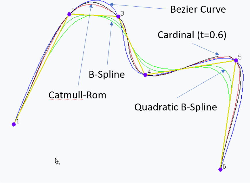
- Quadratic Bézier Curves
- Requires three control points
- Does not pass through the middle control point
- Cubic Bézier Curves
- Requires four control points
- Passes through the first and last points only
- Can be chained into long, composite curves which do pass through control points
- Cardinal Splines
- Requires a minimum of three control points
- Pass through all control points
- Have a tension parameter
- Catmull-Rom Splines
- A special case of cardinal splines (with the tension set to 0.5)
- Requires a minimum of three control points
- Always pass through every control point
- Comes in "uniform", "chordal", and "centripetal" variants
- Quadratic B-Splines
- Requires a minimum of three control points
- Do not pass through all control points
- Entire curve is contained within the convex hull of the control points
- Cubic B-Splines
- Requires a minimum of four control points
- Do not pass through all control points
- Entire curve is contained within the convex hull of the control points
- The Continuity of Splines (An excellent video describing splines. If you only click on one link on this page, this link should be the one.)
How Litchi Generates Traditional Curved Missions
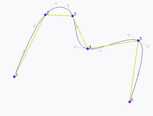
Litchi's traditional curved mission system is not a pure spline, even though it may look like one. Instead, Litchi:
- Connects waypoints with straight lines
- Replaces each interior corner with a quadratic Bézier curve or B-spline
- Lets the user control the curve size at each waypoint
This approach has several consequences:
- The flight path does not pass through interior waypoints
- The flight path always stays inside the convex hull of the control points
- The curvature at each waypoint can be adjusted which is something that cannot be done with a composite spline
Details
How DJI Fly Generates its Waypoint Path
Upon initial inspection, the flight path created using DJI Fly might appear to be generated by using a composite cubic Bézier curve because the curve goes through the waypoints and the composite Bézier is a commonly used method to do this.
A cubic Bézier curve uses exactly four control points and only passes through the first and last of those points. However, it is a common practice to take each pair of consecutive points in a desired curve and fit a Bézier curve to those two waypoints by computing the two inner control points such that the actual waypoints have "C2" continuity with the next Bézier curve. This is called a composite Bézier curve. The process of computing the inner control points is done through the use of the mathematically elegant Gaussian elimination (row reduction) method.
However, upon close inspection, it can be seen that the shape of a DJI Fly waypoint mission near its endpoints is not typical of a composite Bézier curve and hint at another type of curve.
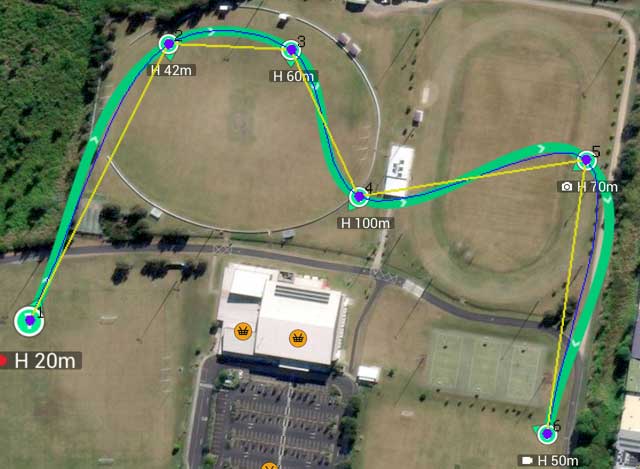
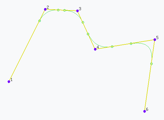
As it turns out, the waypoint path generated by DJI Fly appears to use a curve very similar to a centripetal Catmull-Rom spline. This is evident from the way the path behaves near the endpoints, where the control points are effectively mirrored. Mirroring the endpoints is a known requirement for Catmull-Rom splines to ensure the curve actually passes through the first and last waypoints. I compared the DJI Fly path against several common spline formulations, and the centripetal Catmull-Rom variant provided the closest overall match.
The image on the right shows a centripetal Catmull-Rom spline overlaid onto a DJI Fly mission path. The two curves align very closely around the interior waypoints. However, small differences near the endpoints suggest that DJI is applying endpoint constraints that differ slightly from those used in a standard Catmull-Rom implementation.